
 The Bahamas
CHURCH KITCHEN DESIGN · NASSAU, THE BAHAMAS
Bahamas Harvest Church Kitchen & Food-Service Design in Nassau
Two kitchens, beverage counters and four mobile food-service layouts in one coordinated project.
GRACE’s design package for Bahamas Harvest Church connects ground-floor production and cold storage with a second-floor kitchen, beverage service and dedicated Burger, Grill, Fry and Sweet House layouts.
Location · Nassau, New Providence, The BahamasScope · Kitchen, beverage-counter and mobile food-service designProject record · Equipment layouts and procurement coordination
01 / THE CHURCH & PROJECT SCOPE
A food-service design package for a church campus
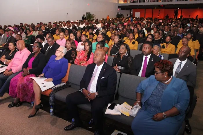
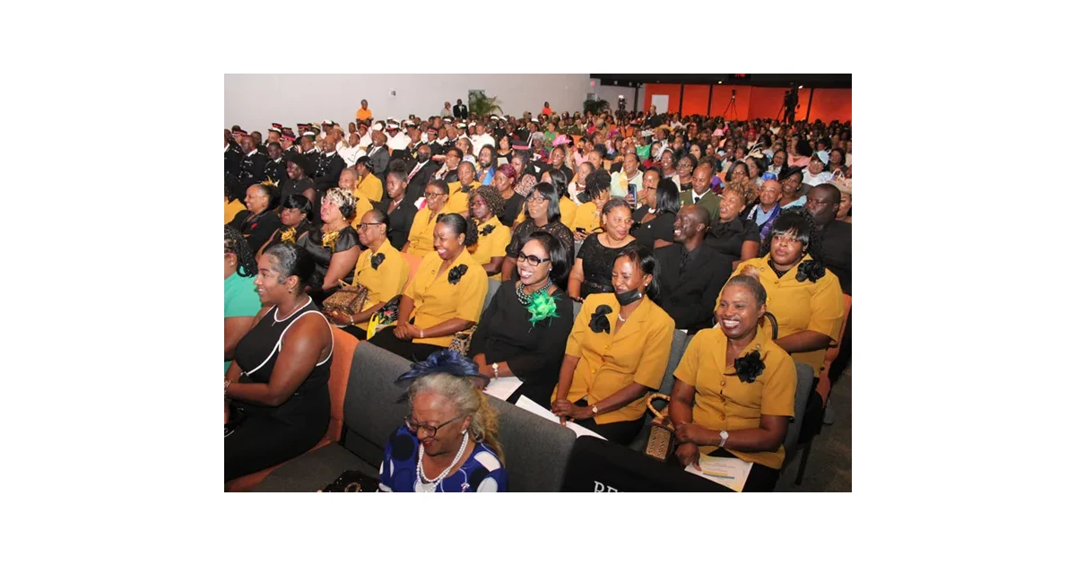
Bahamas Harvest Church is based in Nassau, The Bahamas. The two public event photographs show attendees seated in its auditorium. They introduce the setting; the kitchen design is documented separately in GRACE’s project drawings.
The engineering package covers more than a single cooking room. It brings together cold storage, hot production, dishwashing, beverage preparation and four compact food-service units. Each area has its own equipment arrangement and service requirements.
This case presents documented design and equipment planning. The supplied records do not establish a completed installation, operating meal capacity or measured service results.
02 / PRODUCTION, COLD STORAGE & DISHWASHING
Ground-floor production links cold storage, cooking and wash-up
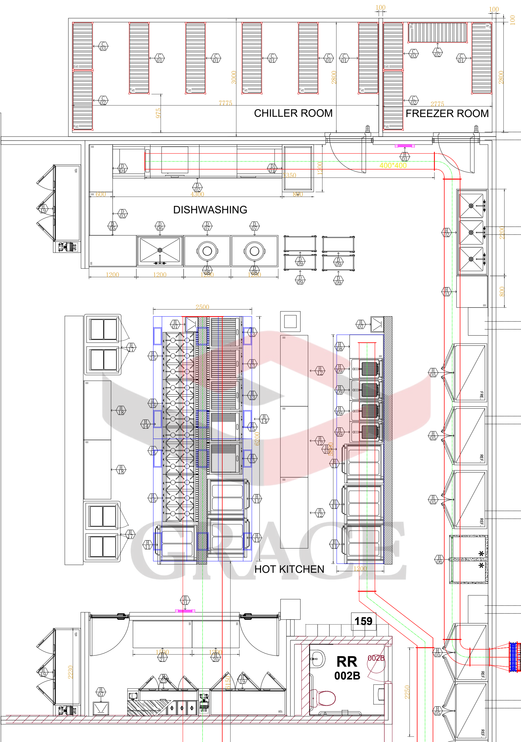
The ground-floor plan connects separate chiller and freezer rooms to the kitchen, with dedicated access doors and shelving arrangements. Dishwashing occupies its own zone beside the hot kitchen.
Cold rooms and working refrigeration
The plan distinguishes bulk cold storage from upright cabinets and refrigerated work counters. This gives the design team separate positions to review for stockholding, preparation and replenishment during service. Door swings and access to shelving remain part of the layout review.
Two central cooking islands
Ranges with ovens, lava-rock grills and griddles form the central cooking arrangement. Fryers and stacked convection ovens occupy additional positions. Worktables and food warmer carts support preparation, landing and holding around the cooking equipment.
A dedicated dishwashing zone
The drawing specifies a long conveyor-style dishwasher, a soaking tank, a large sink, food-waste collection benches and trolleys. Used-item arrival, sorting, washing and clean-item removal need to be coordinated within that zone.
03 / UPPER-FLOOR COOKING & SERVICE
A second-floor kitchen with its own cooking and dishwashing positions
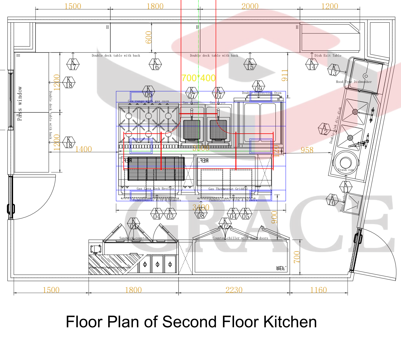
The upper-floor plan uses a central cooking island surrounded by preparation and refrigeration. It labels a pass window, a salad counter, refrigerated drawers, a range with oven, fryers, a griddle, a broiler and a stacked convection oven.
At the right-hand side, sink and dishwashing positions form a separate working edge. The hood-type dishwasher, dish exit table and nearby benches need to be reviewed together so clean racks can leave without occupying the preparation counter. The drawing is a design arrangement; it does not establish an operating throughput.
04 / BEVERAGE PREPARATION & REPLENISHMENT
Beverage service receives a dedicated counter and storage plan
The two counter layouts connect the customer-facing service edge with refrigeration, ice, sinks and replenishment. Their equipment and storage arrangements differ, so each should be coordinated against its own drawing revision.
Ground-floor beverage counter
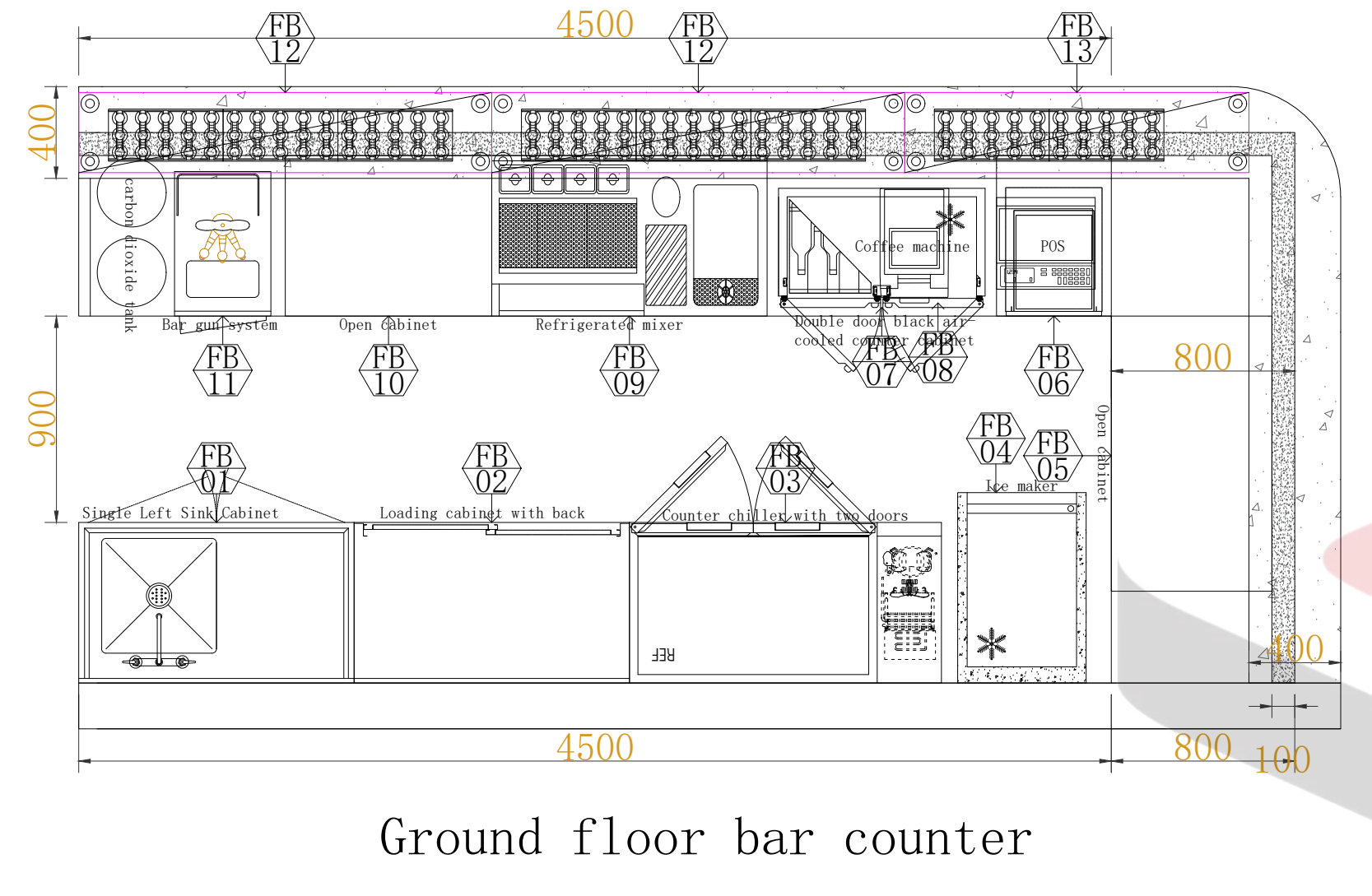
The ground-floor drawing places coffee, ice and beverage equipment opposite a sink and storage run. It also shows overhead glass storage and the relationship between the working counter and the customer counter.
Second-floor beverage counter
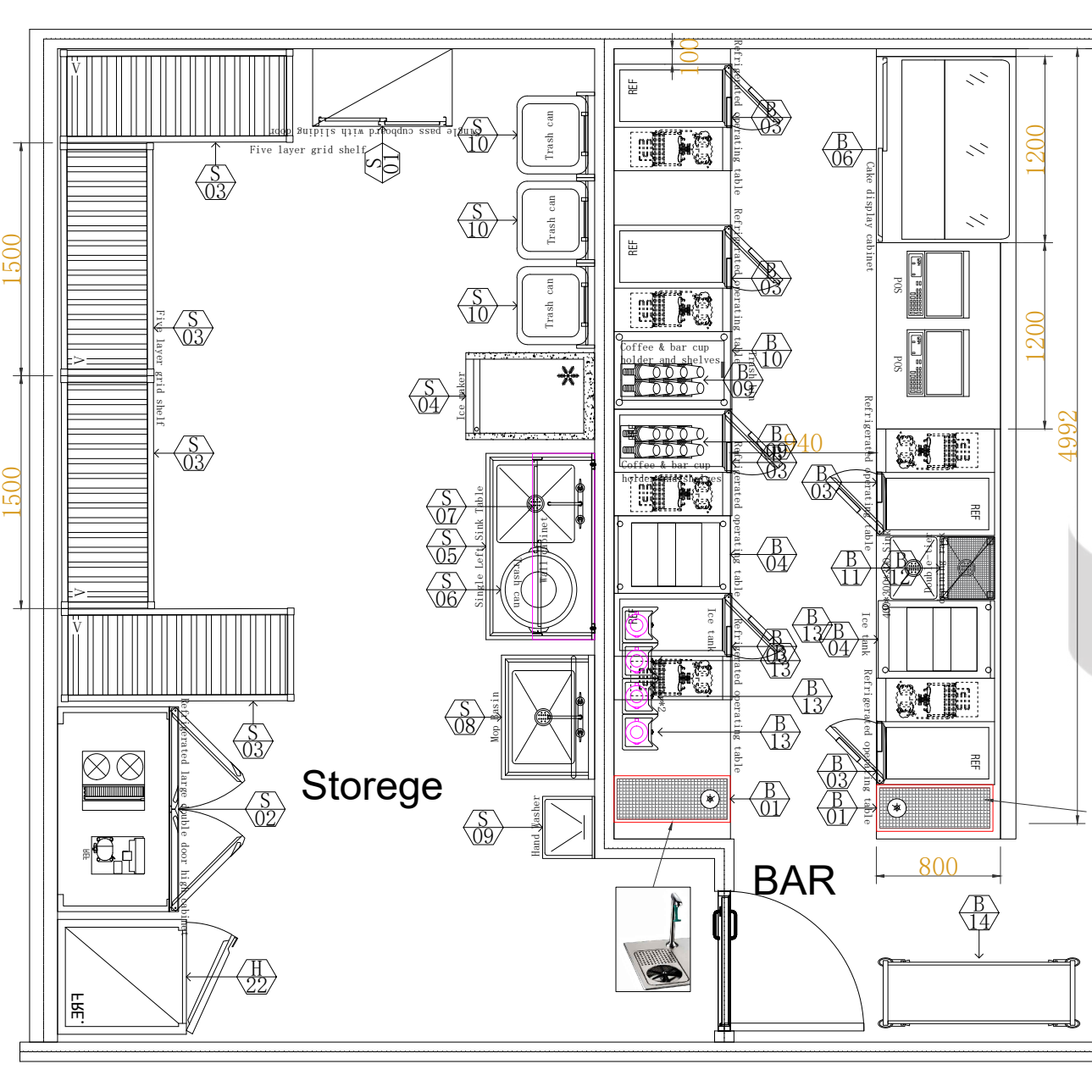
The later upper-floor drawing groups chilled counters, ice wells, cup rinsing, blenders and cake display beside a storage room. The back-of-house area includes shelving, an ice maker, refrigeration, a sink and a mop basin.
05 / BURGER, GRILL, FRY & SWEET HOUSE
Four food-service units, each arranged around a different task
The mobile-unit drawings give each menu format a separate working layout. The dimensions below are the dimensions marked on these plans; they are not stated as licensed vehicle dimensions or certified operating capacities.
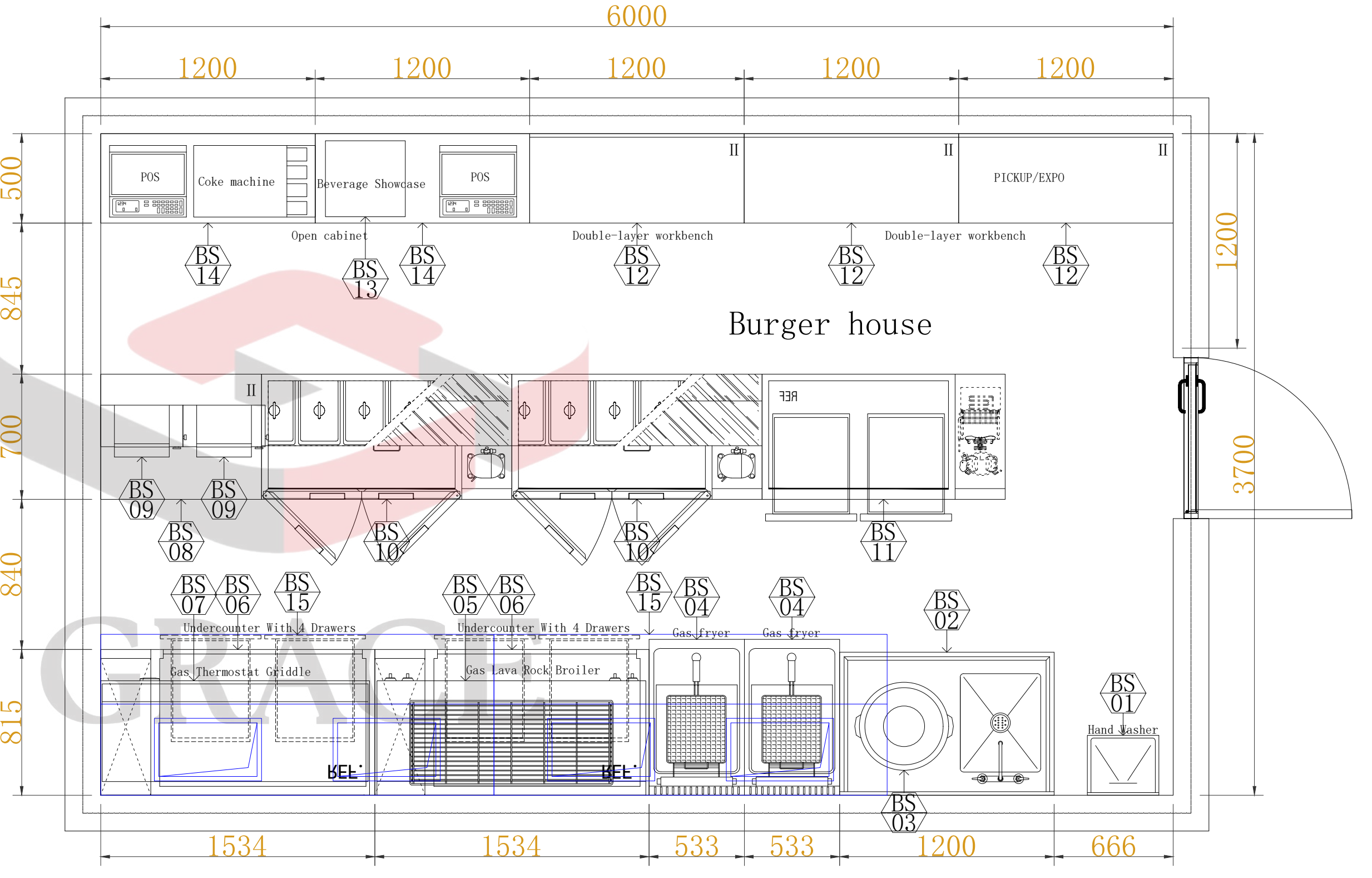
Burger House · 6000 × 3700 mm
The cooking side combines a griddle, broiler and two fryer positions with refrigerated drawers. The opposite side provides preparation, display and pickup/expo space, with a sink and handwashing position at the end of the unit.
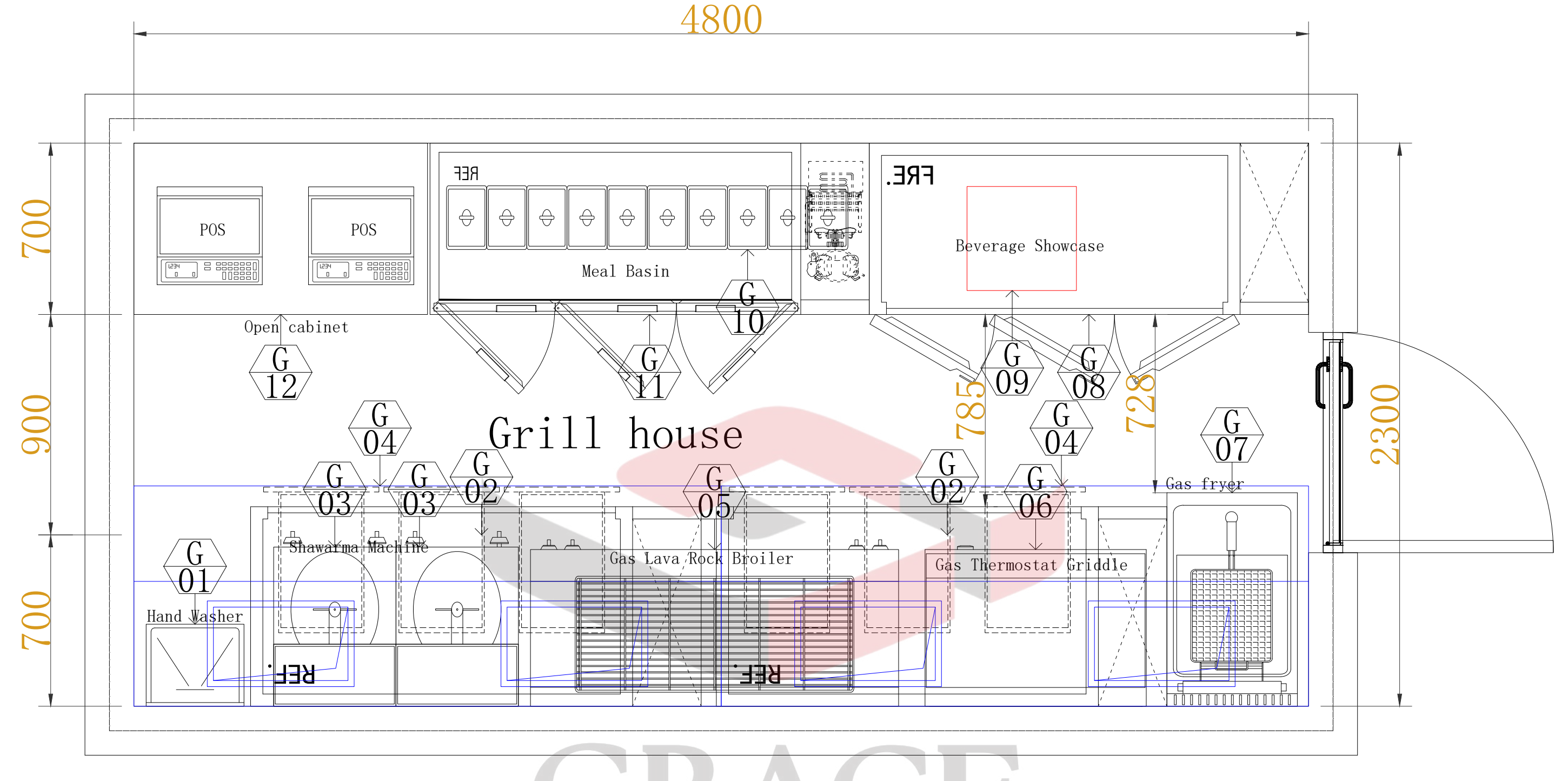
Grill House · 4800 × 2300 mm
This arrangement combines shawarma, broiling, griddle and fryer positions with chilled and frozen storage. The service counter sits opposite the hot line, keeping the handoff edge distinct from the equipment side.
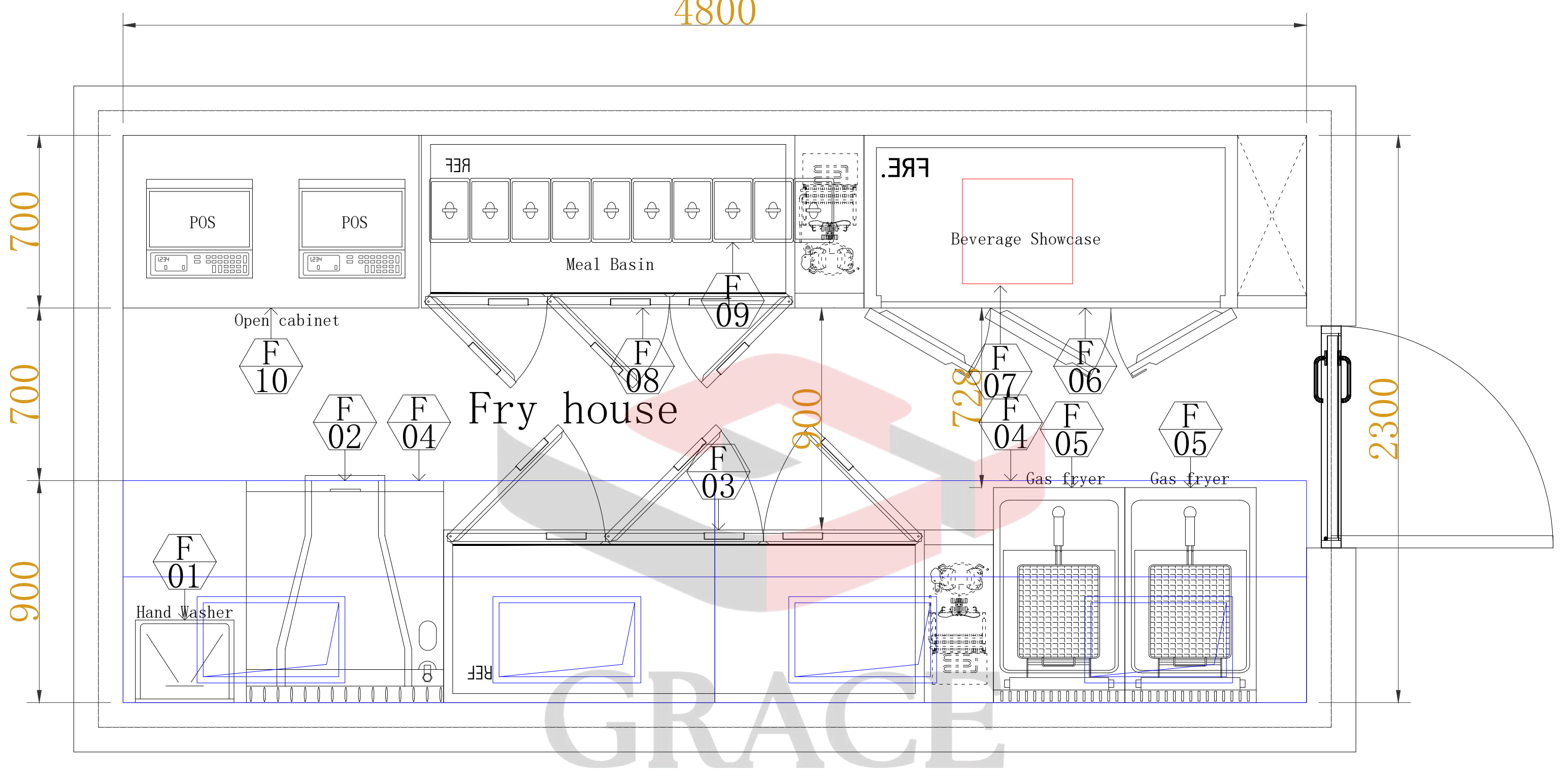
Fry House · 4800 × 2300 mm
The fry-focused plan pairs a tilting frying pan with two fryers and refrigerated counters. A service-pan position and beverage display sit along the opposite counter, while a handwashing position is shown at the end of the cooking run.
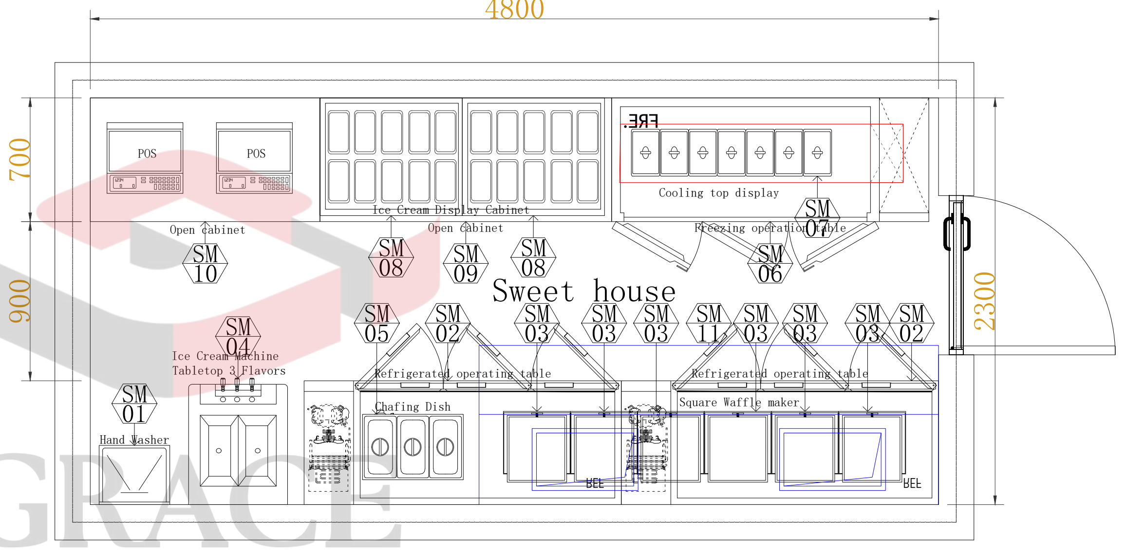
Sweet House · 4800 × 2300 mm
The dessert layout groups waffle preparation, an ice-cream machine, chilled work counters and frozen storage. Display and service occupy the opposite counter. It needs a different power, refrigeration and cleaning schedule from the gas-cooking units.
06 / VENTILATION, UTILITIES & FABRICATION
Coordinate equipment, extraction and services as one package
The kitchen drawings include extraction routes and equipment schedules, while separate mobile-unit files address electrical, water, drainage and gas positions. The next coordination step is to reconcile the current layouts with the actual site and selected appliance versions.
Ventilation and cooking loads
Review hood coverage, duct routes, replacement air and cleaning access with the building-services team. The fan and duct annotations are design information; the final system needs to match the agreed cooking loads and installation conditions.
Power, gas, water and drainage
Check the local electrical supply, phase, frequency and appliance configuration before procurement. Match gas type and pressure to each appliance. Coordinate sinks, ice makers, dishwashers and cleaning points with water treatment and accessible drains.
Refrigeration and replenishment
Agree which ingredients stay in bulk cold rooms and which are held at the working counters. Check door opening space, condenser airflow and stock movement between kitchens, counters and mobile units.
Fabrication and revision control
Match every worktable, sink, cupboard and counter to its drawing tag. Confirm finished dimensions, waste-bin openings, shelves and access panels. Later counter revisions must be checked against the equipment schedule before manufacture.
07 / MODEL REFERENCES
Selected equipment references from the kitchen drawings
These four models appear in the project’s kitchen schedules. The photographs are catalogue illustrations. The dimensions and specifications below are current catalogue references and must be reconciled with the project schedule and the approved appliance version.
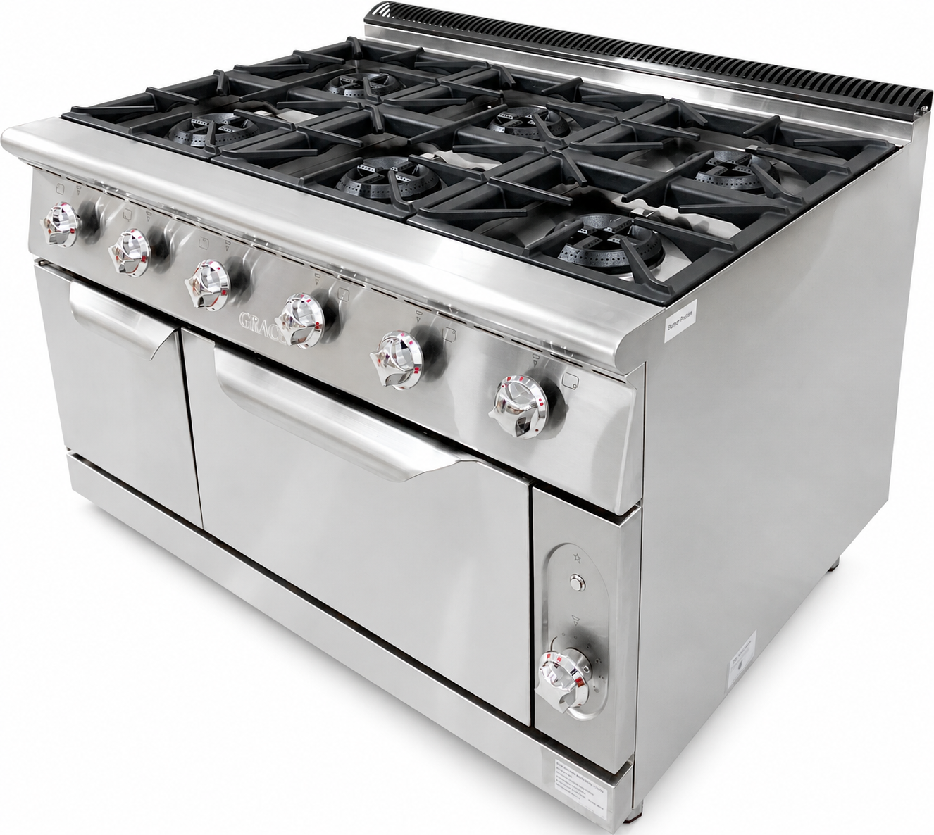
Six-burner range with oven
GR-961
GR-961 appears in both kitchen layouts. The catalogue gives a 1200 × 900 × 920 mm overall envelope and a 38 kW gas input. Confirm fuel configuration, pan work, oven duty and utility positions against the approved cooking island.
Explore cooking equipment →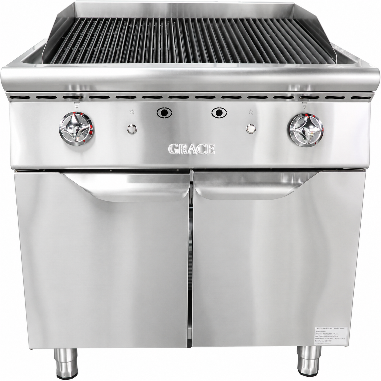
Gas lava-rock grill
GR-902
GR-902 is listed in the ground-floor hot-kitchen schedule. Its catalogue envelope is 800 × 900 × 920 mm, with a 13 kW input. Review the intended grilling duty, landing surface, gas connection and hood coverage.
Explore grilling equipment →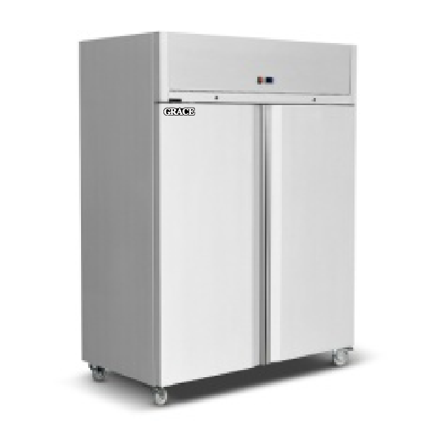
Refrigerador vertical de dos puertas
GR-GN1410TN
GR-GN1410TN appears in the ground-floor schedule. The catalogue lists 1285 L and 1480 × 830 × 2010 mm. Material and electrical variants need confirmation; the illustration does not establish the final project specification.
Explore refrigeration →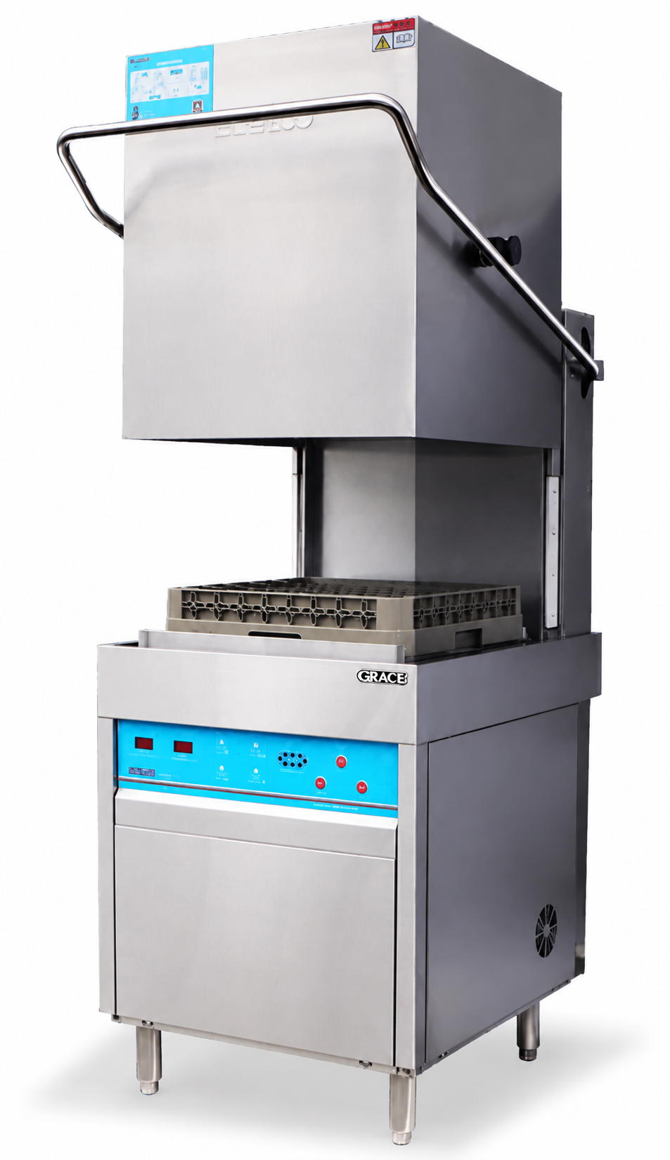
Lavavajillas de capota
GR-60H-A
GR-60H-A is listed in the second-floor kitchen. The catalogue gives 650 × 800 × 1645 mm and 380 V / 11 kW; the project drawing marks a 670 mm width. Resolve that difference before fabricating the connected tables or fixing service points.
Discuss dishwashing coordination →08 / DESIGN COORDINATION & HANDOVER
Bring each service area into one approved equipment schedule
La página commercial kitchen planning connects the appliances with fabricación a medida en acero inoxidable, service positions and utility requirements. For a project with multiple kitchens and counters, the approved layout and tagged schedule need to remain aligned through procurement and installation planning.
Area-by-area layout review
Confirm the measured rooms, circulation, equipment access and handoff positions. Review both kitchens, both beverage counters and each mobile unit as separate working areas within the overall project.
A reconciled technical schedule
Link model, quantity, dimensions, material and site connections to the drawing tags. Resolve catalogue-versus-project differences and record the approved counter revisions before releasing fabrication.
Site and handover coordination
Agree equipment delivery routes, contractor connections and commissioning responsibilities. Provide model-specific operation, cleaning, maintenance and spare-parts information for the equipment ultimately supplied.